| المجموعات الإجتماعية |
| البحث |
| مشاركات اليوم |
 |
| هندسة وصيانة الطائرات Engineering & Aircraft Maintenance يختص بشرح منظومات الطائرة والرد على استفسارات مهندسي الطيران. راجع الفهرس من هنا |
| إضافة رد |
|
|
أدوات الموضوع |
 |
| هندسة وصيانة الطائرات Engineering & Aircraft Maintenance يختص بشرح منظومات الطائرة والرد على استفسارات مهندسي الطيران. راجع الفهرس من هنا |
| إضافة رد |
|
|
أدوات الموضوع |
| مشاركة [ 1 ] | ||||
|
||||
|
|
ACCESSORY SYSTEMS Accessories for gas turbine engines can be divided into two categories: those driven by bleed air taken from the compressor section of the engine; those driven mechanically by an accessory drive shaft and gearbox connected directly to the turbine shaft. The mechanical connection from the turbine shaft may be through an engine-mounted gearbox or through a power takeoff shaft to a remotely mounted gearbox. BLEED-AIR-DRIVEN ACCESSORIES Gas turbines are unique among engines. High-pressure air is available for driving aircraft accessories by air motors or air turbines. Compressor discharge air at high pressure and temperature is bled from the engine through ports provided. This air is ducted as a source of power. It operates the air-conditioning units, hydraulic *****, thrust reverser actuators, and various mechanical actuators in the airplane. Air for cockpit or cabin pressurization is also provided by bleed air from the engine compressor. On multiengined aircraft equipped with pneumatic engine starters, one engine is usually started from an auxiliary power unit or a ground air source. Air from this operating engine is bled through a system of ducts in the aircraft, to power the starters of the other engines. The Pratt and Whitney dual-axial compressor turbine engine is an example that uses bleed air to operate accessories. The JT3D turbofan engine is used on aircraft such as the Boeing 707  and B-52 bomber. This engine also uses a mechanical accessory gearbox. It usually has three separate bleed air systems: high pressure, low pressure, and overboard. The high- and low-pressure systems are used to drive aircraft, engine components, and accessories. The overboard is required to preclude compressor instability. and B-52 bomber. This engine also uses a mechanical accessory gearbox. It usually has three separate bleed air systems: high pressure, low pressure, and overboard. The high- and low-pressure systems are used to drive aircraft, engine components, and accessories. The overboard is required to preclude compressor instability. Compressor bleed air is also used to anti-ice the engine air inlet guide vanes and, frequently, parts of the air inlet duct. Low-pressure air has a pressure of approximately 50 psi and a temperature of more than 300° F. This low-pressure air is taken from bleed air parts compressor mid-section between the low-and high-pressure compressors. High-pressure bleed air has a pressure of about 160 psi and a temperature of more than 650° F when operating near sea level. This air is taken from the rear of the high-pressure compressor. The air available for driving accessories and for other purposes in the aircraft is usually about 3 or 4 percent of the primary engine airflow. Keep in mind the air under pressure that is extracted from the engine is not a bonus. Engine output and fuel consumption are sacrificed. MECHANICALLY DRIVEN ACCESSORIES The other method of driving accessories is a direct, mechanical drive operated by gearing from the compressor-turbine drive shaft. Accessory drives and accessory mounting pads are provided in an engine-mounted, accessory drive gearbox or in a remotely mounted gearbox. On some turbojet engines, accessory pads and mechanically powered drives are also provided in the engine nose section. For dual compressor, axial-flow engines, the main accessory drive gearbox usually receives its power from the high-pressure compressor drive shaft. Mechanically driven accessories include: tachometers, generators (alternators), hydraulic *****, fuel *****, oil *****, fuel controls, starters, and (ii some instances) water *****. LYCOMING T-55 ENGINE The power extraction system transmits power from the N1 and N2 systems to the accessory gearbox located at the 6 o'clock position on the inlet housing (Figures 8-1, 8-2). Most of these components receive their driving force from the N1 system. A minimum amount of power is extracted from the N2 system. 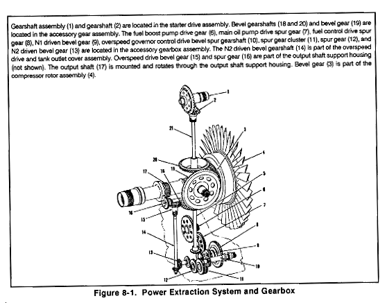 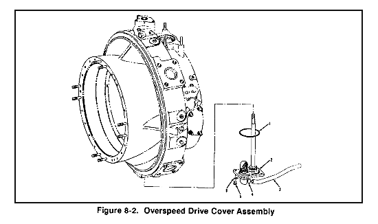 The starter gearbox, mounted at the 12 o'clock position, functions as a centrifuge for air-oil separation during engine operation. The N1 system provides the driving force. A single bevel gear is located at the front end of the compressor shaft; meshes with a planetary gear train housed in the inlet housing This gear train transmits N1 power through two drive shafts: one to the starter gearbox, the other to the accessory gearbox to drive the idler system. A gear located on the output power shaft interconnects with the 90° angle gear in the output shaft support housing. The gears drive the N2 section of the accessory gear train. The N2 driven overspeed governor in the fuel control is driven from a spur gear. This gear is attached to the N2 system drive shaft which rotates on a ball bearing with a pad, located at the 6 o'clock position on the inlet housing Customer power extraction is provided through the vertical bevel pinion gear located within the accessory gear carrier. It is available for use by inserting a customer-supplied drive shaft in its internal splines. The accessory drive gearbox supplies mounting pads for the engine-supporting accessories and provides the transmission capability to drive these components. Dimensional standardization permits interchanging components among engines and eliminates the need for adapters for test equipment. GENERAL ELECTRIC T-701 The accessory module mounts on the cold section module at the 12 o'clock position of the main frame (Figures 8-3, 8-4). It includes the accessory drive gearbox (AGB) that is driven by a bevel-gear system from the compressor rotor via a radial drive shaft. Several accessories are contained in or mounted on the front and rear casings of the AGB. The rear face provides drive pads for the engine starter, hydromechanical unit, inlet separator blower, and a face-ported pad for the overspeed and drain valve. Pads for the alternator and fuel boost pump are on the front face. A cavity is provided for the lube and scavenge pump and chip detector. Pads are supplied for the oil cooler, fuel meter, and lube filter. Cored passages in the AGB housing convey fuel and oil between components. 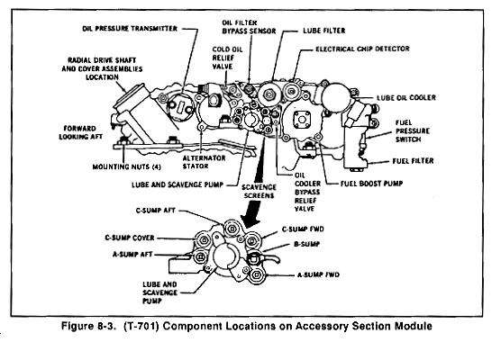 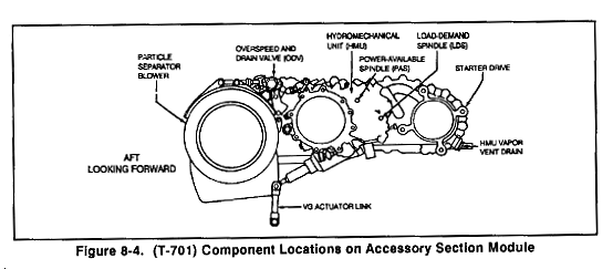 Drive pad seals for the starter, hydromechanical unit, and fuel boost pump drain into a common cored passage in the AGB housing. It then drains to an external port on the right-hand side of the mainframe. ACCESSORY DRIVES Accessory Drive System The accessory drive system provides drives for both the N1 driven accessory gearbox and the N2 driven overspeed governor and tachometer drive assembly. Provision is also made within the system for the drive of customer-furnished accessories through the power takeoff pad located at the 2 o'clock position on the engine inlet housing (Figure 8-5). 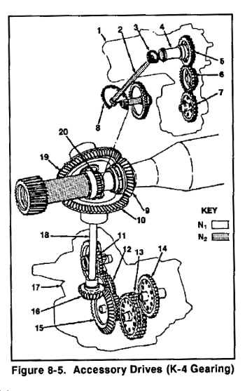 N1 drive is provided from a pinion gear (9) mounted on the forward end of the compressor rotor shaft, driving two bevel gears (10 and 19) located within the accessory gear carrier. The bevel gear located at the 6 o'clock position within the carrier, being the accessory gearbox drive gear (10), is splined internally to accept the accessory gearbox shaft (18). This drive shaft connects the gear carrier to the accessory gearbox through the 90° pinion gear (16) which in turn is splined directly to the starter-generator drive gear (15). The starter-generator drive gear provides drive to all subordinate gears located with the accessory gearbox housing. The power takeoff drive is provided through the second bevel gear (19) located within the accessory gear carrier and is used to drive airframe accessories. The N2-driven overspeed governor and tachometer drive gearbox (1) receives its drive from a spur gear (20) pressed to the power shaft aft of the sun gear. This gear engages the N2 drive and driven gear package (8) located within the accessory gear carrier. This package, a series of three gears, provides an internal spline drive for the drive shaft (2) which passes up through the 10 o'clock inlet housing strut and into the gearbox (l). The drive shaft then engages the internal splines of the upper drive gear (3) which provides drive to the tachometer gear (5). This gear meshes directly with an idler gear (6) which in turn transmits the drive to the combination torquemeter boost pump and overspeed governor drive gear (7). Main Accessory Drive Gearbox The accessory drive gearbox (Figure 8-6) is mounted at the 6 o'clock position of the engine inlet housing and is driven through bevel gears from the front end of the compressor rotor. Drive pads are provided on the rear of the gearbox for the fuel control, the starter-generator, and the gas producer (nI) tachometer generator. The gearbox front side has mounting for the rotary oil pump and also has an unused drive pad with connection line. Oil scavenge lines are connected at the right rear on the gearbox which serves as an oil collector sump, kept practically empty by the pump. A chip detector plug is located in the lower right side, and the oil filter is on the left side. A drain line from the inlet guide vane actuator is connected to the right side. 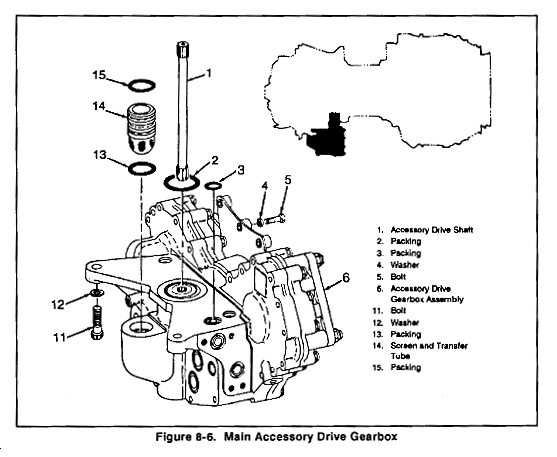 Power and Accessory Gearbox The main power and accessory drive gear trains are enclosed in a single gear case. The gear case serves as the structural support of the engine. All engine components, including the engine-mounted accessories, are attached to the case. At 100 percent engine speed, reduction gearing reduces power turbine speed from 33,290 to 6016 RPM at the output drive pads. The power turbine gear train has a torquemeter to measure engine output torque. Accessories driven by the power turbine gear train are the power turbine tachometer-generator (N2) and the power turbine governor. The gas producer gear train drives the oil pump, fuel pump, gas producer fuel control, and tachometer-generator (N1). The gearbox has a spare accessory mounting pad which is driven by the gas producer gear train. During starting the starter-generator cranks the engine through the gas producer gear train. After completion of the starting cycle, the starter-generator functions as a generator.
هدا الموضوع ماخود من https://www.globalsecurity.org/milita.../1-506/Ch8.htm |
|||
|
|

|
| مشاركة [ 2 ] | ||||
|
||||
|
|
الرجاء من كاتب الموضوع الرجوع الى الرابط التالي للأهمية
https://www.flyingway.com/vb/showthread.php?t=27806 |
|||
|
|

|