| المجموعات الإجتماعية |
| البحث |
| مشاركات اليوم |
 |
| قسم الطيران اللاسلكي AIRCRAFT R/C مناقشات عامه تجارب ودروس تقارير استفسارات راجع فهرس القسم قبل طرح موضوعك >> فهرس قسم الريموت |
| موضوع مغلق |
|
|
أدوات الموضوع |
 |
| قسم الطيران اللاسلكي AIRCRAFT R/C مناقشات عامه تجارب ودروس تقارير استفسارات راجع فهرس القسم قبل طرح موضوعك >> فهرس قسم الريموت |
| موضوع مغلق |
|
|
أدوات الموضوع |
| مشاركة [ 1 ] | ||||
|
||||
|
|
isclosed on Kenneth Moller's Ramjet Forum - 07 August 2003:
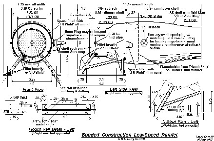 [COLOR="] [COLOR="] 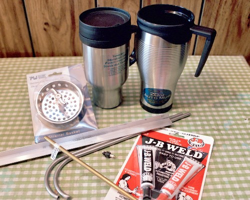 II. The tubular truss engine mounts [28 August 2003]: Previous section Next section Back to Contents Top of page Page 2 Page 3 Subscribe to jetZILLA Online Magazine (it's FREE!) Gluing up an N-strut in my first gluing jig - the opposite strut, semi-finished, and the fully cut rails are to the left. The rails are .5 x .75 x 1/16 inch aluminum angle; the N-struts are cut from the .25 OD titanium tubing contributed by my friend Mark 'Thixis': 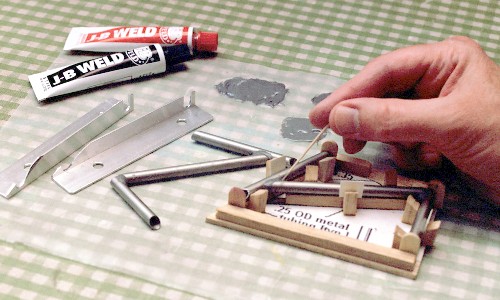 The N-struts resting against a cardboard jig to align them properly, with just enough J-B Weld to tack them to the rails: 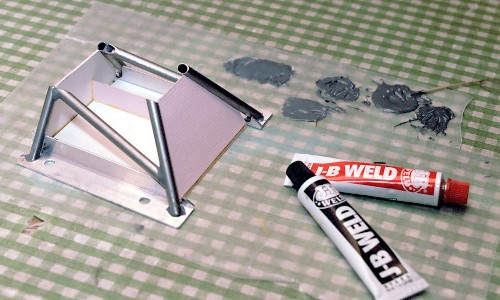 The finished engine mounts, fully reinforced with J-B Weld - left mount in foreground, right mount behind: 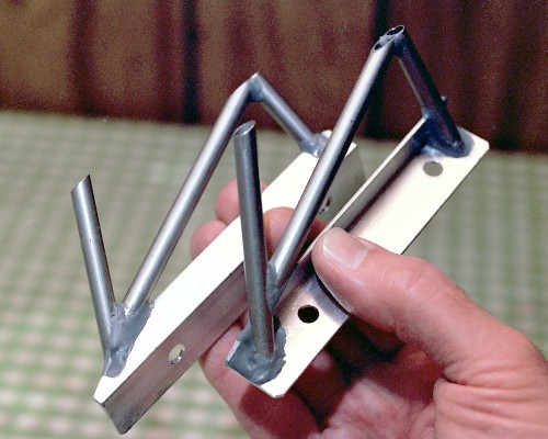 III. Building the diffuser section [04 September 2003]: Previous section Next section Back to Contents Top of page Page 2 Page 3 Subscribe to jetZILLA Online Magazine (it's FREE!) Here's a shot of cutting the groove around the mug shell. The mug is rotated counterclockwise as seen from the top, with the saw oriented as shown [for a left-handed blacksmith, set it all up just the opposite way round]. I oiled the hacksaw blade, but couldn't tell whether this really helped any - it was slow going: 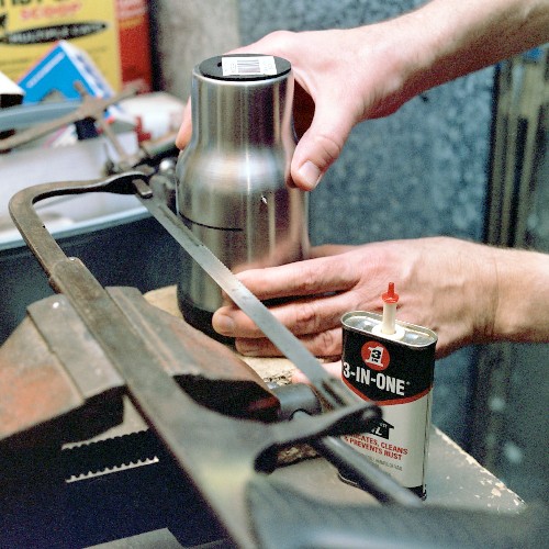 I tried starting the cut with the jeweler's saw, but found it impossible to get a good starting cut, so I just ended up working my way around it with the hacksaw until I knew I'd gotten fully through it all around. The piece had to be moved in the vise jaws four or five times: 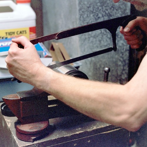 Oddly, the lower part of the shell was not that easy to remove, because of the friction of the insulating foam tightly formed inside: 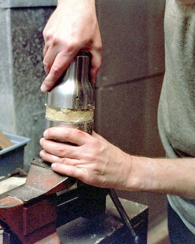 Finally, though, it does break free: 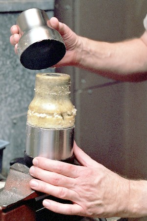 The edge requires a few minutes of work with a flat file and a small half-round file to make it safe to handle: 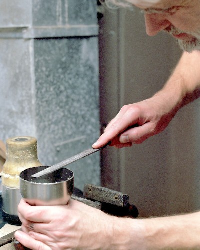 When I scraped off the non-skid ring attached to the end, I was pleasantly surprised to find two little holes, so it was easy to thread the jeweler's saw through to get a good start on the cut. I just worked my way around, a bit inside the edge of the flat end. Again, the piece had to be re-chucked in the vise a few times; and, as predicted, I went through 6 or 7 saw blades to get the whole end cut out. Unfortunately, neither the blade nor the progressing saw kerf shows in the picture, since they are about the width of a horse hair. It took about 45 minutes of sawing and changing blades to complete the cut: 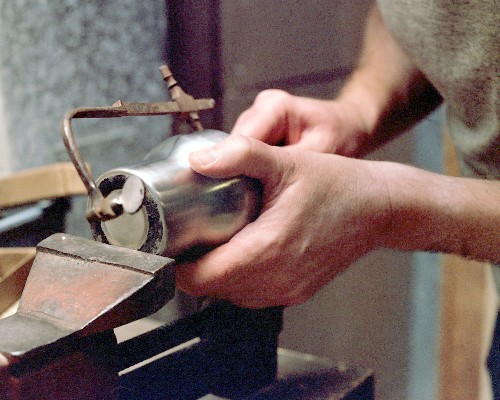 Even though the jeweler's saw is capable of accurate work, I didn't try for real smoothness or precision. A fairly coarse half-round file was perfect for evening up the hole - this only took ten minutes or so: 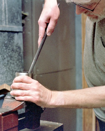 Then, a much smaller and finer half-round was used to smooth up the opening for safe handling and inlet streamlining: 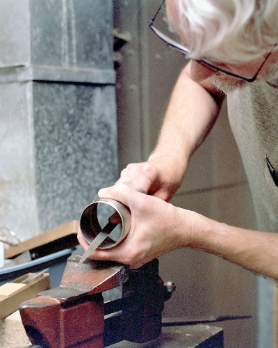 The finished diffuser behind the 'draggy flameholder'. All the small parts of the sink basket strainer are removed and discarded. Note the wonderful array of apertures in this high-quality stainless strainer - a near-perfect 'burner grill': 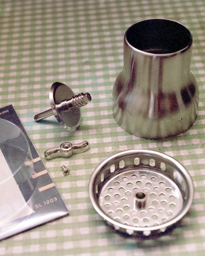 Both the inside edge of the diffuser [large end] and the entire rolled rim of the flameholder have been roughened with sandpaper. A small bead of J-B Weld has been applied to the INSIDE of the diffuser rim. Here, I apply a HEAVY bead of J-B Weld over the whole surface of the flameholder rim: 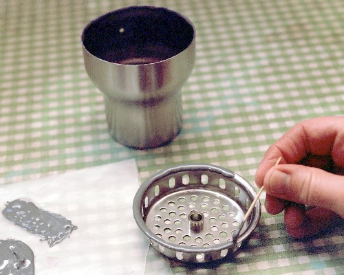 When the diffuser is inverted and lowered into place on this rim, the two beads of cement will blend together to form a smooth, strong 'glue fillet' that will lock the pieces together without the chance of even the slightest gap, with just the slightest bead of J-B Weld visible all around the outside. IV. Bonding the diffuser/flameholder subassembly to the combustion chamber/nozzle shell [12 September 2003]: Previous section Next section Back to Contents Top of page Page 2 Page 3 Subscribe to jetZILLA Online Magazine (it's FREE!) There is a significant gap [a couple of millimeters] between the OD of the rear of the diffuser assembly and the ID of the front edge of the combustor shell. A ring of solid J-B Weld is formed around the diffuser rear edge to a depth of about 3/8 inch [about 8mm] to take up this difference. Believe it or not, the TOP inside plastic rim of the Wal-Mart mug looked like just the right dimensions to work as a mold for this epoxy ring. The trick is to make sure the J-B Weld sticks to the stainless but not to the plastic; so I smeared a thin coating of vegetable oil all over the plastic rim internal surfaces. Then, a heavy coating of J-B Weld was run around the rear diffuser where the flameholder is bonded on, and this is then lowered, flameholder down, into the top of the mug. J-B Weld is added by toothpick to finish filling the gap, right up past the top of the plastic rim: 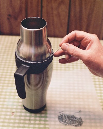 The fingertip is used to smooth out the top edge and remove the slight excess. The thin film of J-B Weld left on the outside of the diffuser shell is of no consequence: 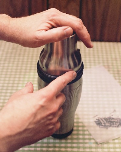 After allowing full curing time, the finished molded ring is popped out of the mold by wiggling the diffuser [it comes out easily] - note the inevitable small air voids; these will be individually filled in with J-B Weld during the operation of bonding to the combustor shell: 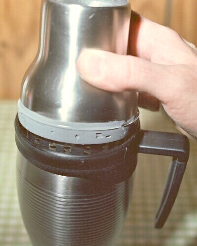 Now the Wal-Mart mug is disassembled, and the top rim of the stainless shell is smoothed with a small file to remove slight burrs. This is a trial fit of the epoxy ring into the edge of the shell. Note the formed ridge of epoxy; the shell slides easily over the main body of the ring, but balks at this ridge, which will assure that the shell is perfectly aligned with the diffuser assembly: 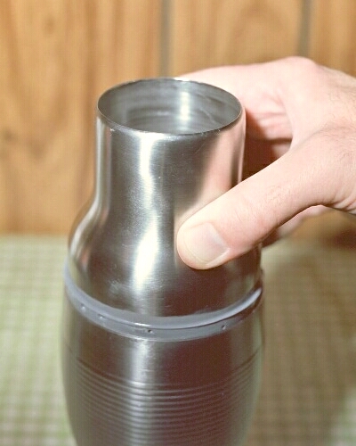 The epoxy ring must be cleaned thoroughly with strong alcohol to make sure there is no residue of the cooking oil. Using medium sandpaper to roughen the inside edge of the shell to ensure solid bonding [this area is also de-greased with strong alcohol]: 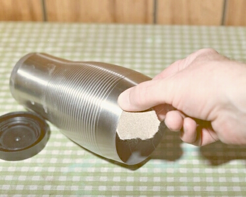 Finally, the entire outer surface of the epoxy ring is coated with J-B Weld and the little voids are all filled in. Then, a HEAVY bead of J-B Weld is applied all around the INSIDE of the front edge of the shell. The diffuser assembly is inverted and the shell is lowered into place around it, until it comes to rest on the molded ridge. This is the orientation it is left in until the bond is fully cured. Here, I wipe excess epoxy off the outside with a dry paper towel; the residual film will be removed by a little fine sanding: 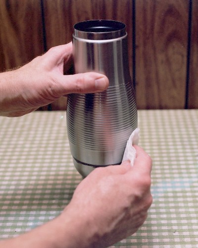 [/COLOR] [/COLOR]
|
|||
|
|
| مشاركة [ 2 ] | ||||
|
||||
|
|
[COLOR="]twisted tight:
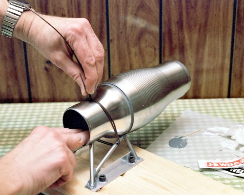 The mounts are secured, accurately aligned, to a piece of flat scrap wood, using 1/4-20 hex head bolts & washers, with 'tee nuts' underneath. Forming the streamlining fillet at the front edge of the combustor shell. This is along the bottom side, before the little hole was filed into being a slot: 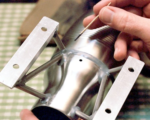 Here's a fine shot of Maggie, basically assembled, but before drilling out for the fuel pipe & spark plug: 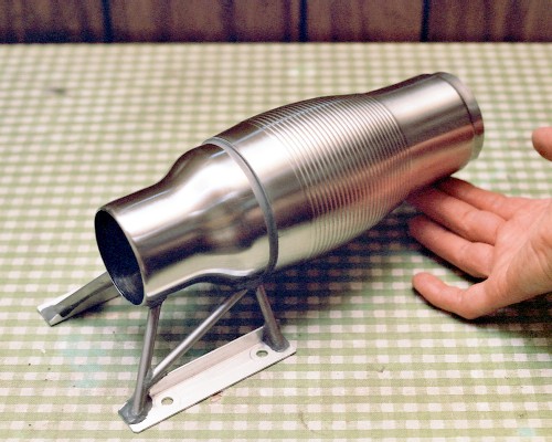 VI. Details, details [22 September 2003]: Previous section Next section Back to Contents Top of page Page 1 Page 3 Subscribe to jetZILLA Online Magazine (it's FREE!) The flattened and kinked end of the pressure tube. This part will protrude slightly beyond the inside wall of the large part of the diffuser, so the cut end will lie along the presumed flow path. The tubing is 1/4-inch OD brass. The flattening is to limit leakage from the diffuser shell when a gauge is not attached; only a trickle of air is needed to pressurize the gauge. 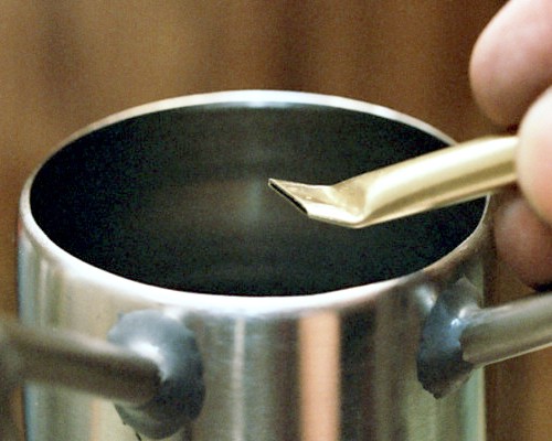 The hole that used to hold the bottom end of the mug handle is lengthened into a slot, using a Heller needle file. The slot is cut in line with rearward airflow, but is slanted to one side for the flattened tube end: 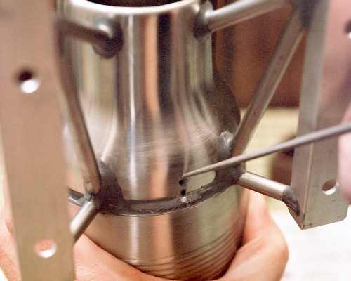 Preparing to test fit the flattened end of the pressure tube. This shows approximately the final orientation and location -- the outer end of the tube extends forward and down, out through the lower space in the left-side N-strut: 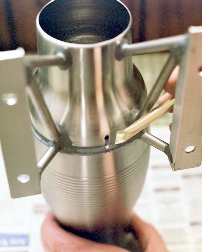 Because of the thinness of the shell, the spark plug hole was drilled small and filed out with another of the Heller miniature files. This one is similar to a half-round, except that both sides are round but ground to two different radii: 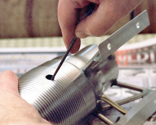 The bottom side of the engine, showing the fully bonded engine mounts and pressure gauge tube, with the spark plug temporarily mounted [exact location of the plug is not critical]: 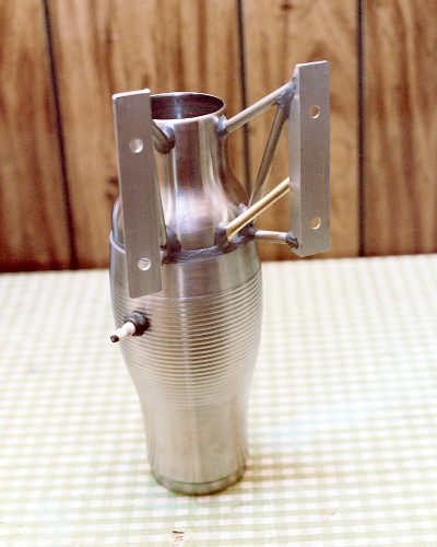 The fuel pipe mounting will be cut from a standard 1/4-inch stainless tubing fitting. First, the fitting is drilled out 1/4- inch ID all the way through, so the tube can pass clear through it into the intake: 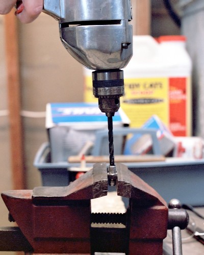 The hardest saw cut in the entire project: Cutting off the bottom [pipe thread] end of the fitting. I finally bought a new hacksaw blade, and the work went MUCH faster. This will leave the machine- thread part of the fitting to protrude through the hole in the shell from the inside, with a thin, hexagonal flange for bonding. The cut surface will be filed smooth, and the hole edge chamfered for smooth passage of the fuel pipe: 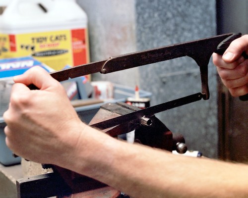 VII. Fuel and ignition system work [29 September 2003]: Previous section Next section Back to Contents Top of page Page 1 Page 3 Subscribe to jetZILLA Online Magazine (it's FREE!) The spark plug ready to mount in the combustor shell. The box-end wrench is fitted with a short piece of masking tape to hold the plug mount nut up at the wrench surface, making it easy to get it into place inside the hole so the plug can simply be threaded in. The electrical lug is filed out to fit the plug; it not only acts as the spark plug washer, but as a contact for the ground side of the high-voltage ignition system during starting. 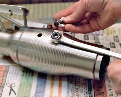 Parts of the fuel pipe mount, after cutting and filing - from the left: the outer bonnet nut, slip ring, collet, finished mount stud, and the cut-off end [pipe-threaded end, to be discarded]. 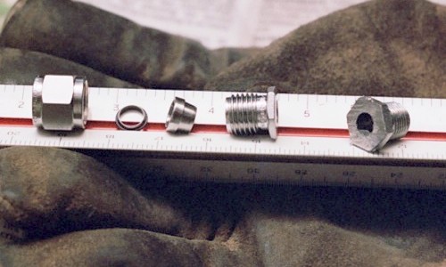 The fuel pipe mount stud ready to mount. The stud will pass through the hole from the inside. Above it is the Heller needle file used to bring the hole out just large enough for the stud to pass through. 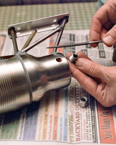 Using the full length of the raw 1/4-inch brass tube to hold the pipe mount stud in alignment as we wait for the J-B Weld to harden: 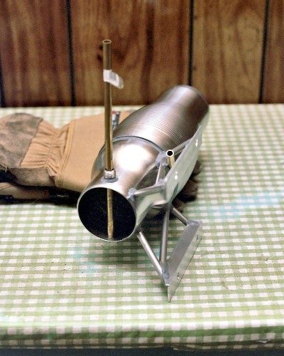 Inside view of the finished fuel pipe mount, in place. You can just make out the smooth fillet of J-B Weld all around the hex flange that forms the base of the mount: 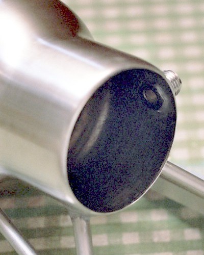 Outside view of the finished fuel pipe mount, fully filleted in with J-B Weld: 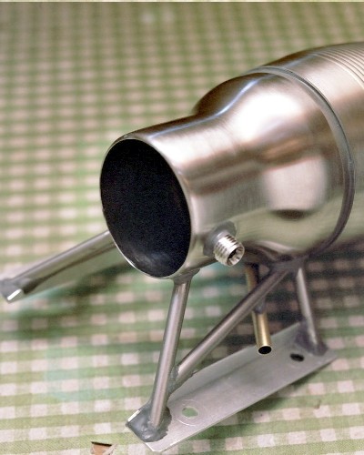 The first fuel pipe shown in place in the fuel pipe mount. It is made from 1/4-inch brass tubing, and is nothing but a simple tube with the end plugged with a dollop of J-B Weld, and a 1/16-inch hole drilled clear through, just behind the plug. This very simple pipe should be suitable for propane testing, using an external valve to regulate the flow; the liquid-fuel tube will have its own needle valve permanently attached to the external end of the tube. 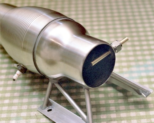 The engine so far, along with the tools used in mounting the plug. A six-point socket, as shown here, should be used around the plug body, to prevent slipping off and breaking the porcelain insulator. The tape can still be seen attached to the 12-point box-end wrench used to reach inside the engine to hold the plug mount nut. Also shown is the soon-to-be modified Super Tigre needle valve assembly, which at $18.00 US turned out to be the most expensive single part of the entire engine. 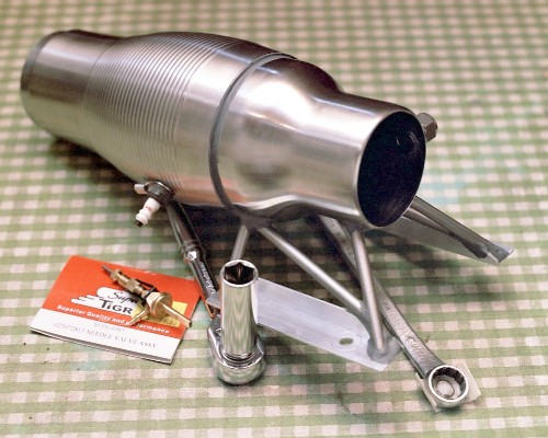 The jeweler's saw turned out to be an easy way to remove the short, cylindrical ring at the tail end of the engine. Once the cut was started, it was worked all the way around, keeping fairly close to the rolled zone [about 3/8 inch forward of the rim].  Finally, a decent shot of the jeweler's saw in action! Cutting off the short machined inner end of the Super Tigre needle valve body: 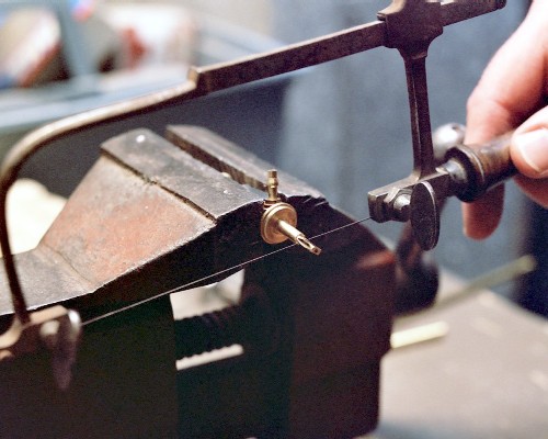 VIII. Finishing up [03 October 2003]: Previous section Next section Back to Contents Top of page Page 1 Page 3 Subscribe to jetZILLA Online Magazine (it's FREE!) The parts of the fuel tube [liquid fuel version]: The main tube is 3/16-inch OD brass tubing, the shoulder tube is 1/4-inch tubing. The tiny part to the left of the main needle valve body is the small machined end that was being removed in the previous photo; it will be discarded. The needle valve entrance pipe and main valve body have been 'ported' out with a jeweler's drill to an approximately .055 inch ID. 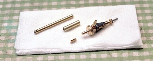 The fully finished fuel pipe for liquid fuels. The thin film of J-B Weld at the left end of the shoulder pipe will be easily cleaned up with a few strokes of fine sandpaper. 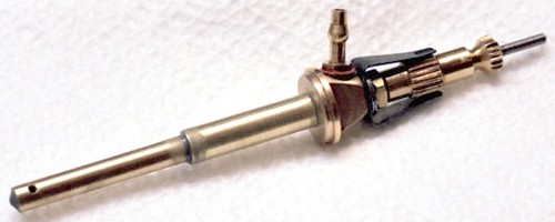 The fuel pipe going into the pipe mount. The bonnet nut is slid on, followed by the properly-oriented slip ring and the collet. Then the whole assembly is inserted into the mount and slid in until the metering holes at the far end of the pipe are perfectly centered in the intake opening.  The new fuel pipe fully installed, just after tightening up with an adjustable wrench. It is not necessary to tighten the nut excessively; just enough to keep the pipe from rotating as the needle valve is adjusted.  The cut end of the exhaust nozzle is smoothed up with a good-sized half-round file ... 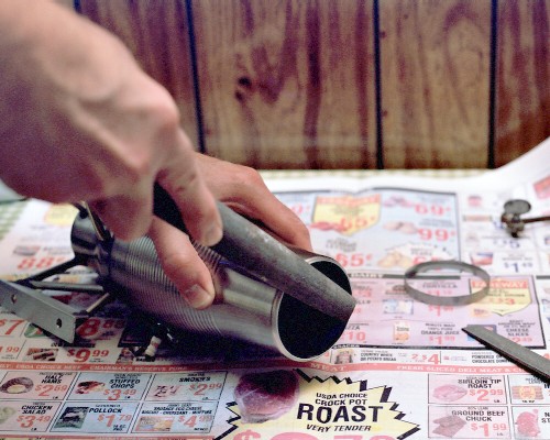 ... and finished with a smaller one: 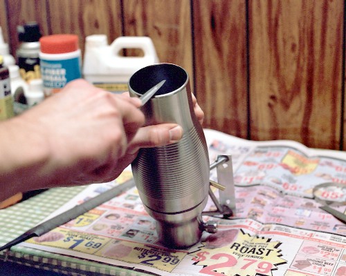 The end result is a smooth opening with just enough 'rolled edge' left intact to strengthen the rim: 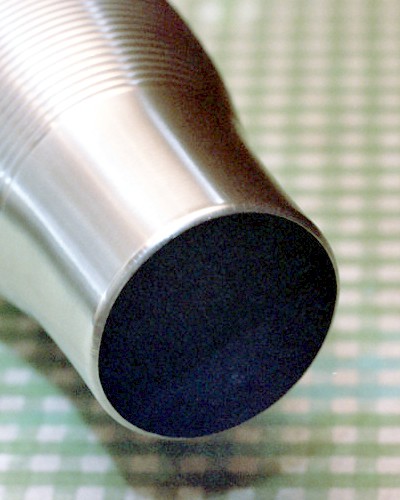 Maggie Muggs, finished at last - finished weight 10.6 ounces [0.66 pound]: 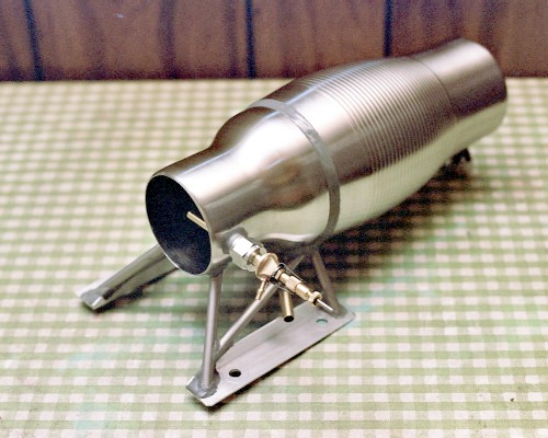 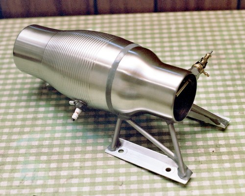 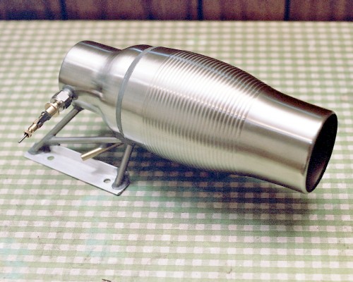 [/COLOR] [/COLOR]
|
|||
|
|
| مشاركة [ 3 ] | ||||
|
||||
|
|
[COLOR="]standard 'shop vac', and it seems to work well enough:
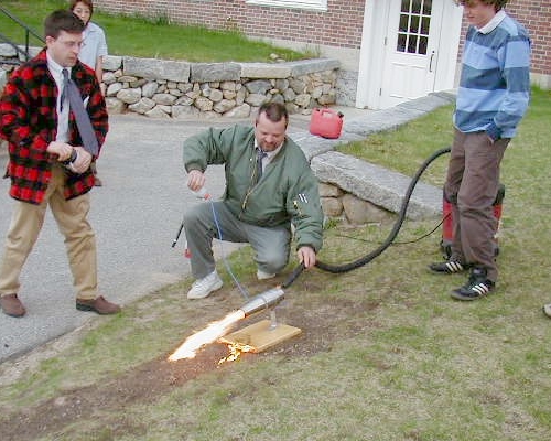 When more airflow and/or less fuel flow is applied, the flame starts to look somewhat better - we're moving towards "lean" combustion: 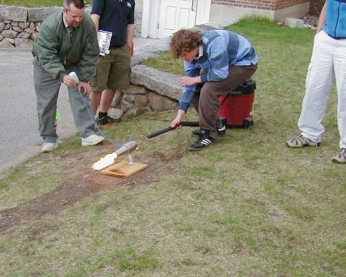 Continuing to lean out the burn. It looks like there's enough flame and noise at this point that the test run is beginning to draw a crowd. The mug parts were from teachers that were willing to donate their used coffee mugs to the project, so these parts aren't exactly like the ones shown in the plans; note, however, how Ben chose a mug shell that has a well-developed combustion chamber zone and a good long, smooth cone for the tail section - exactly the right approach! 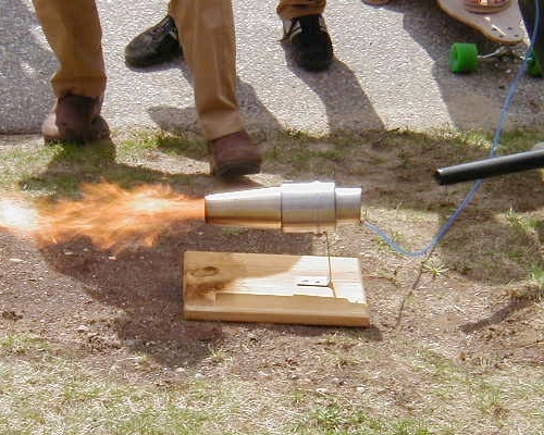 Leaning out the combustion even more makes the flame much less visible, but significantly louder [note that the unlookers are starting to back off a little!]. The sink strainer flameholder is one of the few parts that had to be purchased new for the project; it keeps the flame back in the tail section where we need it [unfortunately, the flameholder can't be seen in any of these photos]: 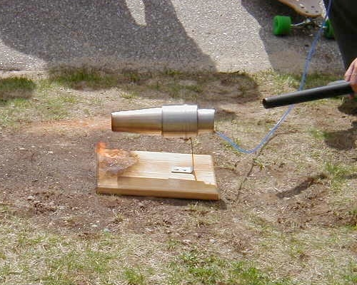 Once you get a really good lean run, the noise is a pretty intense 'jet noise' roar, and in daylight the visible flame almost disappears. This is exactly the way your jet ought to be running. However, this is also a very hot way to run, and the epoxy construction can't be expected to take this for too long: 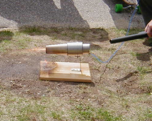 [/COLOR] [/COLOR]
|
|||
|
|
| مشاركة [ 4 ] | ||||
|
||||
|
|
أخي الكريم هذا شئ في قمة الرؤوعة والإبداع إنه يتم صناعة محرك نفاث بهذا الشكل المبسط
نحن معك بكل مانملك ماأخبارك في الصناعة هل بدأت؟ |
|||
|
|
| مشاركة [ 5 ] | ||||
|
||||
|
|
هل تسمي هذا الشئ محرك نفاث؟؟؟؟؟؟؟؟؟؟
|
|||
|
|
| مشاركة [ 6 ] | |||
|
|||
|
درجة الضيافة
|
انه فعلا ابداع..وبسيط لاكنه للأسف محرك تضاغطي..اي لا يعمل الا مع السرعات العالية..لذلك قاموا بجلب المكنسة الكهربائية لزيادة تتدفق الهواء..: (
نحتاج الى ضاغط ومروحه...كهيكل تصميمه رائع..لاكن هناك بقية.. شكرا لك اخي.. تحيتي.. |
||
|
|
| مشاركة [ 7 ] | ||||
|
||||
|
|
ما شاء الله
والله روعه وحرافه والصراحه من ناحيتي ما اعرف اسوي لو ايش اسير ههههههههه. تحياتي لكم بالتوفيق والنجاح |
|||
|
|
| مشاركة [ 8 ] | ||||
|
||||
|
|
اخي ابو نواف فعلا نلاحظ ان المحرك مايحتوي توربينات لكنه يشتغل بمبدأ النفث
|
|||
|
|
| مشاركة [ 9 ] | ||||
|
||||
|
|
يا شباب انا اصنع في المحرك ولكني احتاج الى ضاغط لاضعه هنا
[IMG]file:///C:/DOCUME%7E1/soumer/LOCALS%7E1/Temp/moz-screenshot-5.jpg[/IMG] [IMG]file:///C:/DOCUME%7E1/soumer/LOCALS%7E1/Temp/moz-screenshot-2.jpg[/IMG][IMG]file:///C:/DOCUME%7E1/soumer/LOCALS%7E1/Temp/moz-screenshot-3.jpg[/IMG] [IMG]file:///C:/DOCUME%7E1/soumer/LOCALS%7E1/Temp/moz-screenshot-4.jpg[/IMG] |
|||
|
|
| مشاركة [ 10 ] | ||||
|
||||
|
|
هنا
[IMG]file:///C:/DOCUME%7E1/soumer/LOCALS%7E1/Temp/moz-screenshot-6.jpg[/IMG][IMG]file:///C:/DOCUME%7E1/soumer/LOCALS%7E1/Temp/moz-screenshot-7.jpg[/IMG] |
|||
|
|
| مشاركة [ 11 ] | ||||
|
||||
|
|
سامحوني ساضع الضاغط هنا

|
|||
|
|
| مشاركة [ 12 ] | ||||
|
||||
|
|

|
|||
|
|
| مشاركة [ 13 ] | ||||
|
||||
|
|
|
|||
|
|
| مشاركة [ 14 ] | ||||
|
||||
|
|
جميل جدا صنع محرك نفاث بهذا الشكل
بصراحة أنا بدات أجمع بعض الأفكار حول الضغاط والتوربينات أخوي محمد ايش رأيك تصنع التوربينات من مادة البلاتينيوم ولا في صعوبة في الحصول عليها؟ |
|||
|
|
| مشاركة [ 15 ] | ||||
|
||||
|
|
أنا معك في صنع المحرك هذا بكل ماملكت وياليت باقي الإخوة الاعضاء يشاركو لان إذا تمكنا من صنع محرك نفاث سيكون إنجاز كبير ومفيد وموفر
|
|||
|
|
| مشاركة [ 16 ] | ||||
|
||||
|
|
      
|
|||
|
|
| مشاركة [ 17 ] | ||||
|
||||
|
|
أخي الكريم لا تنسى أنه لابد من حدوث تغيير في التخطيط عن إضافة المكثف والطراد
|
|||
|
|
| مشاركة [ 18 ] | ||||
|
||||
|
|
يا اخي عبد السلام انا متشكر وماعاد احتاج الا الضاغط فارجو من اعضاء المنتدى ان يساعدوني فانا اليوم اشتريت حاقنة الوقود وصمغ الحديد AB والبوجي وما عاد احتاج الا الضاغط
|
|||
|
|
| مشاركة [ 19 ] | |||
|
|||
|
عضو خط الطيران
|
شباب انا والله اقدر اسوي محرك بس وين وكيف وابغى لي ورشه
واسوي محرك يدفع بقوه هائله |
||
|
|
| مشاركة [ 20 ] | ||||
|
||||
|
|
كابتن محمد أنا معاك لكن كيف ضغاط بلا طراد هل تنوي صنع المحرك بدون طراد لكن الطراد ضروري جدا لزيادة قوة النفث والدفع
وهتحتاج عمود مثبت في وسط المحرك عشان تثبت فيه الضغاط وبالنسبة للبوجيه هتشغله بقوة كم فولت ؟ ممكن لو سمكت تشرح لي دائرة تشغيل البوجيه والله يوفقك |
|||
|
|
| مشاركة [ 21 ] | ||||
|
||||
|
|
ولا تنسى إضافة رمان البلي لتوازن العمود ليه ما تضع صور عشان نستفيد معاك إذا كنت هتستخدم بوجيه بيشتغل ب12 فولت استخدم البنزين كوقود
|
|||
|
|
| مشاركة [ 22 ] | ||||
|
||||
|
|
لكن أخي الكريم هناك نقطة في قمة الأهمية أليس لابد من الطراد لأن سوف يدور بواسطة الغازات الخارجة وبالتالي يدور الضغاط
كيف يدور الضغاط بلا طراد ؟؟؟؟؟؟!!!1 |
|||
|
|
| مشاركة [ 23 ] | ||||
|
||||
|
|
[
المواد التي تحصلت عليها ] 
|
|||
|
|
| مشاركة [ 24 ] | ||||
|
||||
|
|
أنصحك تراجع الموضوع هذا للكابتن سوررو لأنه مهم جدا بيتكلم عن نفس موضوعنا
https://www.flyingway.com/vb/showthre...t=17242&page=3 |
|||
|
|
| مشاركة [ 25 ] | ||||
|
||||
|
|
الفكره جميله وبصراحه عاجبني الراجل اللي عمل النفاث لأنه متحري الدقه في كل شئ حتي تغيير انواع السنفره ... ولكن انا لست ملم بهذه الاشياء الخاصه بالنفاسات ... لذلك لا معني لتقييمي للعمل .. ولكن سأقيم العضو الذي طرح الموضوع لأن الافكار الجديده تغذي المنتدي وتنعشه وتخرجه عن الاطار الاعتيادي .. وتلهم الكثييير في بدء محاولات للعمل
|
|||
|
|
| مشاركة [ 26 ] | ||||
|
||||
|
|
أخي العزيز روش حتى أنا بدأت أجمع المعلومات المهمة والمواد المطلوبة لصنع محرك بالشكل الرائع ده لكن ماهي المادة إل أصنع منها التوربين والمكثف لازم تكون خفيفة ومتحملة لدرجات الحرارة العالية ؟
|
|||
|
|
| مشاركة [ 27 ] | |||
|
|||
|
مخالف قوانين المنتدى
|
|
||
|
|
| مشاركة [ 28 ] | ||||
|
||||
|
|
ما شاء الله جميل و لكن هل يمكن عمله بالحقيق؟؟ لأن المحرك النفاث يحتاج معيره أصعب من العادي....
و شكرا! |
|||
|
|
| مشاركة [ 29 ] | ||||
|
||||
|
|
والله زين ولكن المعدن راح يذوب .
|
|||
|
|
| مشاركة [ 30 ] | ||||
|
||||
|
|
يا جماعه صاحب الموضوع يتكلم عن pulse jet وانتم خلطتوا الاوراق مع المحرك turbine jet
الفرق بينهم انه صاحب الموضوع يعطيه العافيه كان يقصد نوع من المحركات الكل يقدر يسويه مجرد ماصوره وبوجي ووقود ( ماصوره بشكل معين ) ويكون طرد للغازات من الخلف مع العلم انه صعب التحكم في سرعته او ما يسمى الثروتل يعني اذا بغيت تسوي لاندنق لازم يطفى ( هذا الي شفته من مقاطع الفيديو ) ما اذكر شفت محرك pulse jet الا وتنزل الطياره وهو طافي محركات الpulse jet حرارتها عاليه ولا يمكن تشغلها لوقت طويل بدون ما تطير في الغالب المعدن يذوب بعكس الجت العادي والمشهور الجت العادي يحتوي على blades في الداخل تدور بسرعات عاليه تصل الى 300 الف دوره بالدقيقه وهي من اجل ضغط الهواء في الداخل وانفجاره مع الفيول خروجه بسرعه عاليه تقاس بقوه الثرست كل ما كان الثرست اعلى كانت قوة الدفع اعلى ثاني شي الجت العادي صنعه شبه مستحيل ( ما اقول مستحيل لكن صعب جدا ) والسبب انه لا يتوفر لك الرولمان الخاص فيه ( مصنوع من السيراميك ) من اجل تحمل درجات الحراره العاليه اظن الاخ سلمان ( النجم الشمالي) كان له تجربه بالموضوع هذا والسبب الي خلاه يوقف المشروع حسب ظني هو عدم توفر رولمان السيراميكالخاص بالجيت سالت الكابتن مامون وهو من المشهورين في هذا المجال ولهم معرفه قديمه عن ال pulse jet فقالي لا يهممممك ابد ازعاج على غير فايده ههههه لكن الي يحمسني لتجربته هو سهوله صننعه مثل ما شفتوا ببدايه الموضوع مجرد تشكيل معين لماصوره طويله وفيها سبارك بلق فيه نوعين من الجتات الي كتبها صاحب الموضوع واحد بصمام ويعطي عزم اكثر والثاني بدون صمام ولكن عزم اقل واخطر والسبب في خطورته هو احتمالية انه الغازات ترجع للمقدمه بعكس ما هو مخطط لها تروح للخلف ان شاء الله اذا عندي او لقيت معلومات اكثر راح نطرحها لكم والله يوفق الجميع واسف على الاطاله اذا فيه خطاء صححوا لي تحياتي لكم جميعا |
|||
|
|
| موضوع مغلق |
 قسم الطيران اللاسلكي AIRCRAFT R/C
|
|
|
| أدوات الموضوع | إبحث في الموضوع |
|
|
|
 المواضيع المتشابهه
|
||||
| الموضوع | المنتدى | |||
| تعلم صنع محرك نفاث | قسم الطيران اللاسلكي AIRCRAFT R/C | |||
| فكرة لصنع محرك نفاث | قسم الطيران اللاسلكي AIRCRAFT R/C | |||
| صناعة محرك نفاث | قسم الطيران اللاسلكي AIRCRAFT R/C | |||
| طيار أنشفط داخل محرك نفاث ................. | قسم الصور | |||
| محرك نفاث | قسم الطيران اللاسلكي AIRCRAFT R/C | |||